Pipelines and Gathering Systems
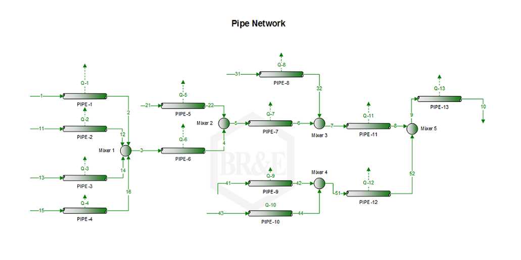
Pipelines and pipeline networks for above ground, buried, and subsea conditions may be simulated, including known
or calculated heat losses to the environment.
- Model horizontal, vertical, and inclined pipelines
- Predict locations of drip condensate
-
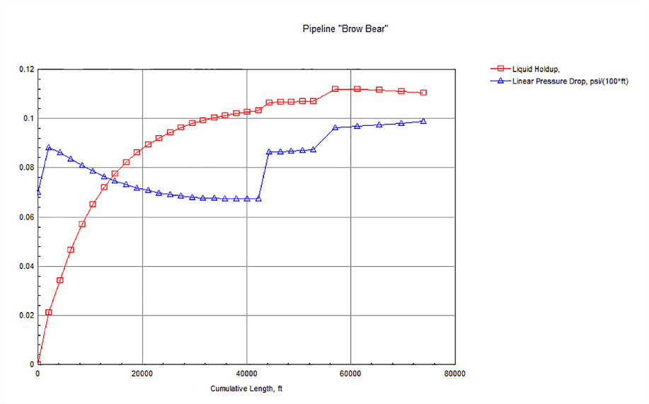
Predict liquid holdup and volumes from pigging operations
- Optimize compressor discharge pressures to balance system nodes
- Monitor cricondentherm, heating values, and other parameters throughout pipeline networks
- Predict solids formation in a pipeline
Pipeline Details
-
The Pipeline block calculates the pressure drop, temperature change, velocity, flow regime, and other properties
of a single- or multiphase stream as it flows through segments of pipe.
-
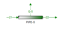
The pipeline has one Process Stream inlet, one Process Stream outlet, and an optional Energy Stream attachment.
-
The pipeline may include any number of segments, each with different specifications.
-
In addition, a segment may be a fitting, valve, or reducer between any two segments of pipe. Fitting equivalent length or Kv can be used. Default values are taken from either based upon the Crane Technical Paper No. 410 (1991) or from Table 5-19 in Perry and Chilton (1973).
-
Execution may proceed upstream through the Pipeline (i.e. Pipeline supports forward and backward calculation).
-
Multiple correlations are available for multiphase flow including: Aziz-Govier-Fogarasi, Beggs and Brill,
Dukler et al, Duns and Ros, Lockhart-Martinelli, Lockhart-Martinelli Modified, Mandhane-Gregory-Aziz, and Orkiszewski
-
Material of construction can be selected from ASME, API, and CSA material grades.
-
Multiple ground types are available for buried or submerged pipe with default thermal conductivities provided, but updateable.
Line Sizing Analysis
-
The Line Sizing Analysis quickly calculates either the minimum diameter that meets the pressure drop specification or
the pressure drop for a fixed pipe diameter.
-
Single or multi-phase systems may be modeled for straight or inclined pipe.
-
MAWP is calculated based on process conditions and application pressure vessel code selected.
-
Individual phase fluid velocities and erosional velocities are calculated.
-
Numerous flow correlations are available.
-
The Line Sizing Analysis assumes that the lengths are relatively short with no heat transfer occurring such that fluid properties are constant.
New Pipeline Features
One area of significant development has been the ProMax pipeline block. Several additional calculations have been added to increase
functionality and put more information at your fingertips, alongside more calculation methods that are based on extensive industry
operating data!
TUFFP Mechanistic Models
The TUFFP mechanistic models (TUFFP Unified and TUFFP Vapor-Liquid) have been developed by Tulsa University Fluid Flow Projects,
which is a cooperative Industry-University research group supported by several oil and gas production, consulting, service member
companies and government agencies.
The TUFFP models are applicable for any inclination angle and calculate the pressure recovery for downward inclined flow.
Having the TUFFP Unified model means that ProMax can now model a true three phase flow!
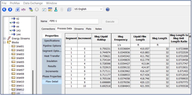
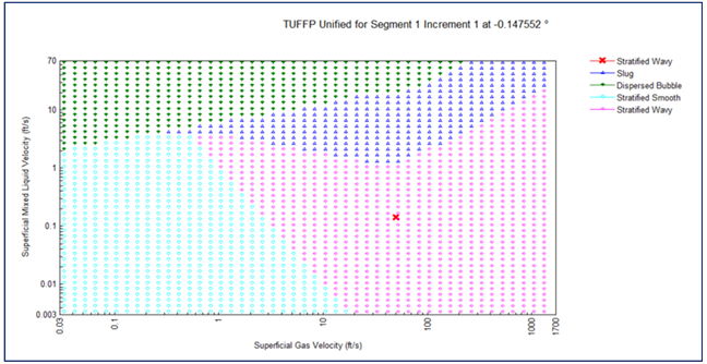
Not only does this model take advantage of a wide range of field data, but it also provides much more detail in terms of phase behavior. When using these models, a new section called “Flow Detail” can be found in the block to display this information.
Other Pipeline Additions
Now each segment will perform the API RP 14E erosional velocity calculation and is displayed in the results section.
The results section will also display the Mach number for each segment, along with the calculated sonic velocity.
Other added multiphase flow correlations including the Petalas and Aziz mechanistic model and the Hagedorn-Brown correlation.
Regime maps in the plots tab, to visually show where current operations fall in the model’s regime scheme.
A new “Flow Efficiency Factor” value that can be used to fit single phase flow results to operating data.
