Sulfur Recovery Unit Modeling
Lili Lyddon
Feb 13, 2007
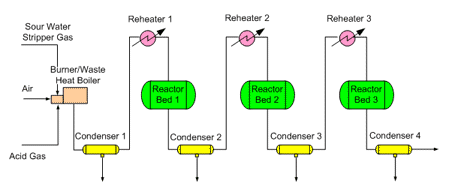
The typical Claus sulfur recovery unit includes an acid gas burner, a waste heat boiler, and sulfur condenser followed by 2, 3, or 4 catalyst bed converters for conversion of H2S and SO2 to sulfur. Each converter is preceded by a reheater and followed by a sulfur condenser.
Alternate or optional reactors might include sulfur partial oxidation (SUPERCLAUS® type), sulfur direct oxidation (Selectox® type), sub-dewpoint Claus beds, or Tail Gas Cleanup Unit (TGCU) hydrogenation reactor. Other reactors include a Reducing Gas Generator (RGG) reactor which is used in conjunction with the TGCU hydrogenation reactor, sulfur burner, or tail gas incinerator.

ProMax can model all of these different Reactors. More than one block is usually required to simulate the burner-waste heat boiler. It is typically modeled as three separate blocks to accurately represent the different reactions occurring in different areas of the reactor: burner, first pass WHB (thermal reaction zone), and 2nd pass WHB (sulfur redistribution zone). The actual burner is modeled as an adiabatic reactor with the "Acid Gas Burner" Gibbs set (see Acid Gas Burner for further details). The first pass of the waste heat boiler is modeled as a temperature-set or non-adiabatic reactor with the "Sulfur Thermal Reaction Zone" Gibbs Set. The second pass of the waste heat boiler is modeled as a "Sulfur Redistribution" Gibbs Set.
Since the specified Gibbs Set determines the reactor function, any icon may be used to represent any type of reactor. Selecting a reactor icon which is indicative of the function allows the user to easily distinguish between reactor types.